Understanding and documenting the Museum’s mechanical, electrical, water, and geothermal systems.
The Museum’s systems are robust, but many components require updated documentation and performance verification. The geothermal well field, domestic water system, heat recovery chiller, and air handling units are key priorities.
Sections:
- Existing Electrical, Lighting and Fire Alarm Systems
- Summary of Mechanical, Plumbing, Fire Protection
- Existing System Observations
Summary of Electrical, Lighting and Fire Alarm System
The Nelson-Atkins Museum of Art benefits from a highly reliable electrical system designed to minimize disruptions. Power is supplied from two independent utility sources, with on-site backup generation and battery systems supporting critical functions in the event of an outage. This layered approach helps protect life safety systems, security, and essential museum operations. While the core electrical infrastructure remains robust, much of it was designed decades ago and is approaching the point where strategic upgrades will be needed to maintain reliability, improve efficiency, and support future technologies.
Across the campus, lighting and life-safety systems reflect a mix of old and new approaches. Many interior and exterior spaces still rely on older lighting technologies that use more energy and offer limited control, while select areas have already transitioned to modern LED fixtures. Similarly, the fire alarm system is comprehensive and well suited to a museum environment, with early smoke detection in key areas to protect collections and occupants. Opportunities exist to modernize lighting and controls to improve energy performance, flexibility, and user experience — while continuing to build on the strong foundation of safety and reliability already in place.
Existing Electrical, Lighting and Fire Alarm Systems
TABLE 1 – Electrical, Lighting and Fire Alarm System Summary
This table summarizes the museum’s major building systems. More detailed technical descriptions are available below for readers who want deeper insight.
| System | What It Does | Current Condition | Why It Matters |
| **Electrical Power** | Brings electricity from the utility into the campus and distributes it to buildings and equipment | Highly reliable with dual utility feeds and backup power, but much of the core equipment is aging | Aging electrical infrastructure can become harder to maintain and may limit future upgrades, even if it still works today |
| **Backup Power (Generator & UPS)** | Keeps critical systems running during power outages | Backup generator and battery systems support essential operations, but some configurations are no longer code-compliant | Ensuring life-safety systems always have power improves safety, reliability, and compliance |
| **Lighting** | Provides interior and exterior illumination for visitors, staff, and collections | Mix of older fluorescent/incandescent lighting and limited LED upgrades; controls are basic | Older lighting uses more energy, costs more to maintain, and limits flexibility and comfort |
| **Lighting Controls** | Turns lights on/off and manages when and where lighting is used | Older on/off relay system with little automation or dimming | Modern controls can save energy, improve user experience, and adapt lighting to actual needs |
| **Fire Alarm System** | Detects fires and alerts occupants and emergency responders | Comprehensive and effective, but core components are aging and harder to service | Modern systems improve early warning, reduce false alarms, and ensure long-term support |
| **Early Smoke Detection (VESDA)** | Detects very small amounts of smoke to protect collections and high-value spaces | Existing system is no longer serviceable, though much of the infrastructure can be reused | Early detection provides more response time and reduces risk to people and collections |
| **Electrical Panels & Distribution** | Routes power safely to different parts of the campus | Some panels are outdated, difficult to access, or no longer meet current standards | Modernized equipment improves safety, simplifies maintenance, and supports future growth |
| **Energy Monitoring (Submetering)** | Tracks where and how electricity is being used | Limited visibility into energy use by building or system | Better data helps staff manage energy costs, plan upgrades, and improve resilience |
| **Microgrid & On-Site Energy (Future Option)** | Allows the campus to generate and manage its own power during outages | Not currently in place; solar and backup power potential identified | A microgrid could improve resilience, reduce emissions, and support long-term sustainability goals |
The facility is served by two independent utility grid sources connected through an existing utility automatic transfer switch (ATS), which feed two separate utility transformers. The incoming utility power is delivered at 15kV and stepped down to 480V for building distribution. The Main Service Entrance equipment is located in the central utility plant (CUP), and encompasses two main 5000A switchgear lineups, MS1 and MS2, with a 5000A Tie breaker for a Main-Tie-Main configuration. These boards then distribute power throughout the facility. A 2500A bus duct supplies power to the Bloch Building, while another 2500A bus duct serves the Main Building. Backup power is provided by a 750kW generator dedicated to critical loads, both life safety and non-life safety loads. There are two UPS Systems – 20kW UPS system and a 30kW UPS system feeding other loads deemed critical by the facility. This dual-source configuration enhances both reliability and maintainability, ensuring minimal to no service interruptions except in the event of a broader utility grid outage. Refer to the attached preliminary one-line diagrams for additional detail.
The facility’s lighting system is primarily composed of older fluorescent and incandescent fixtures, with only certain areas — such as the lower-level northeast portion of the main building, parts of the Bloch Building, and sections of the parking garage—having been retrofitted to LED. As a result, the lighting types and performance levels vary across different portions of the campus. The current lighting control system is a low-voltage relay-based setup that provides standard on/off switching with minimal adjustability. This system offers very limited functionality beyond basic control and does not support more advanced lighting management features.
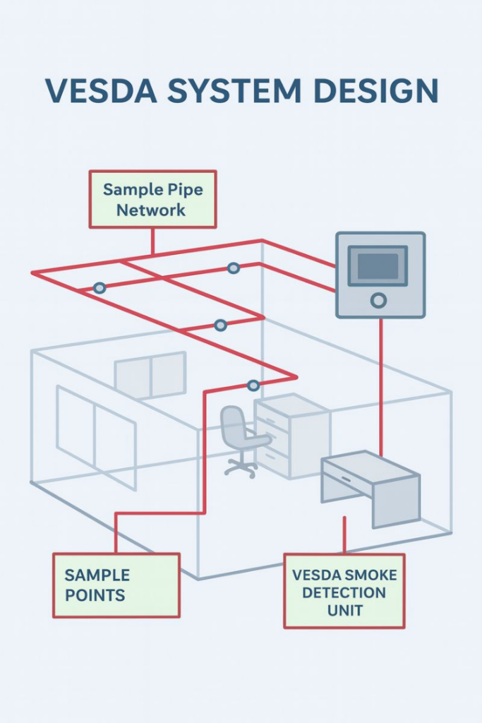
The existing fire alarm system consists of a Simplex 4100U addressable Fire Alarm Control Panel, designed for large-scale applications with support for a wide range of intelligent devices and modules, providing flexible and reliable fire detection. The fire alarm system is found campus wide. Integrated into the system is Simplex VESDA (Very Early Smoke Detection Apparatus), which offers continuous air sampling and highly sensitive early smoke detection, ideal for protecting high-value areas. The current VESDA system primarily resides in the main building. Together, the 4100U and VESDA components form a robust and responsive fire alarm solution, ensuring early warning and effective emergency response capabilities throughout the facility.
Replacement Recommendations
Fire Alarm System Replacement
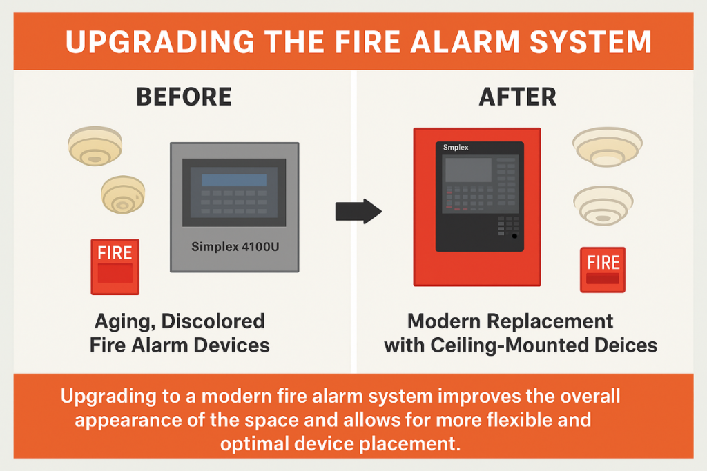
The existing fire alarm devices are discolored and showing signs of age. Replacing them would not only improve the overall appearance of the space but also allow for more flexible and optimal device placement. In addition, facilities typically prefer upgrading from wall-mounted units to ceiling-mounted devices for a cleaner, more modern installation.
A modern replacement for the Simplex 4100U is the Simplex 4100ES or equivalent, which is the current Simplex flagship for addressable fire alarm control units designed for today’s commercial and institutional buildings. The Fire Alarm Systems of today, such as the Simplex 4100ES, offers several important advancements that make it the natural successor to the 4100U. First, it provides significantly increased capacity, supporting up to thousands of addressable points, making it suitable for large campuses, multi-building networks, and complex facilities. Its IP-based networking allows for faster communication, remote diagnostics, and easier integration with building management systems—capabilities the 4100U was never originally designed for. Additionally, the modern systems offer additional notification for appliances addressable detection, which include smart self-testing, improved diagnostics, and much better false-alarm prevention, reducing long-term maintenance and service calls.
Upgrading from a 4100U to a modern Fire Alarm system offers major benefits for life-safety compliance. The modern systems also support mass notification and voice evacuation, both of which are increasingly required in high-occupancy facilities. Its modular design allows integration with firefighter phone systems, suppression release control, and enhanced annunciation options like touchscreens and graphical workstations. These features not only improve emergency response but also help bring older buildings into alignment with current NFPA and local code expectations. Another important reason to upgrade is future support: the 4100U is aging hardware, and sourcing replacement parts or expanding existing systems becomes more difficult each year. The 4100ES, on the other hand, is actively supported, offers backward-compatibility options, and is designed for long-term scalability.
In short, the modern solution to the Simplex 4100U is the Simplex 4100ES or equivalent, and upgrading provides increased system capacity, modern device compatibility, advanced networking, enhanced safety features, better maintenance tools, and long-term supportability. For facilities planning renovations, expansions, or code updates, moving to a modern system ensures the fire alarm system remains reliable, expandable, and compliant for many years to come.
FIGURE 1 – Fire Alarm System Upgrade
VESDA System Replacement
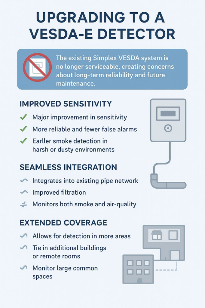
The existing Simplex VESDA system is no longer serviceable, creating concerns about long-term reliability and future maintenance. However, much of the current sampling (sniffing) tubing can remain in place and be reused as part of a new system, minimizing disruption and installation cost. Since the main VESDA unit is located in the main building, this upgrade also presents an ideal opportunity to expand the system and extend coverage across the entire campus.
Upgrading from an older Simplex VESDA system to a VESDA-E detector provides a major improvement in sensitivity, reliability, and early warning capability. The newer “Flair” detection technology in VESDA-E can detect smoke far earlier and with fewer false alarms, even in harsh or dusty environments. This gives building operators more time to respond, reduces nuisance trips, and provides a more stable and dependable fire protection solution.
The current system already uses an aspirating “sniffing” method, so upgrading to a VESDA-E hybrid system would seamlessly integrate into the existing pipe network. Because the core detection concept remains the same, the upgrade focuses on enhancing performance rather than replacing the entire infrastructure. The hybrid detectors would slot into the current system while adding improved sensitivity, better filtration, and the ability to monitor both smoke and indoor air-quality conditions without major changes to how the building’s aspirating system operates.
Additionally, VESDA-E supports significantly longer pipe runs, which opens the door for expanding the detection network across more areas of the campus. This extended coverage capability allows facilities to tie in additional buildings, remote rooms, or large common spaces that could not previously be served by the older system. Overall, the hybrid upgrade provides a straightforward path to improved performance and wider campus-level protection while maximizing the value of the system already in place.
FIGURE 2 – Upgrading to VESDA
Electrical Equipment
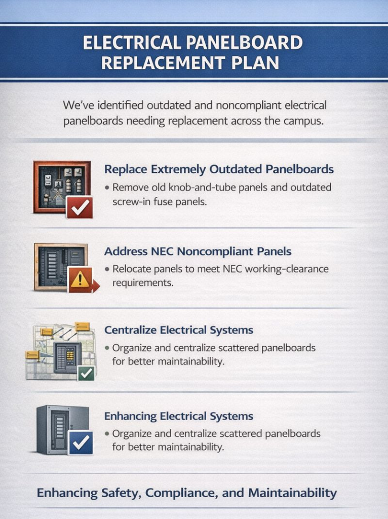
We prepared a list of panelboards throughout the campus that we recommend replacing. Several of the units are extremely outdated, including some that still use old knob-and-tube and screw-in fuses, which are difficult to service and no longer practical for modern maintenance. The list also identifies panelboards that are not compliant with NEC working-clearance requirements. For these, we recommend relocation to achieve proper code compliance.
In addition, many of the existing panelboards are scattered across the campus in a way that makes electrical tracing and system identification challenging. To improve maintainability and streamline future work, we recommend centralizing electrical systems wherever feasible. Please refer to the attached panelboard list for further details.
FIGURE 3 – Replacing Electrical Panelboard
Life Safety Generator
Currently, the life-safety generator is supplying both NFPA life-safety loads and additional facility-desired non-Life Safety loads. This configuration does not meet current code requirements, which mandate that life-safety loads be isolated from non-essential or optional loads. To address this, we recommend separating these loads using two dedicated automatic transfer switches (ATS)—one serving only life-safety systems and the other serving non-life-safety equipment.
Implementing this separation not only brings the system into code compliance but also provides significant operational benefits. With independent ATS units, maintenance or testing on the non-life-safety ATS can be performed without major interruption to critical egress lighting, fire alarm systems, and other essential life-safety functions. This reduces downtime, enhances reliability, and ensures the facility can maintain continuous protection even during service activities.
Lighting Systems
The facility’s lighting system is primarily composed of aging fluorescent and incandescent fixtures, with only select areas—such as the lower-level northeast portion of the main building, parts of the Bloch Building, and the parking garage—converted to LED. Because of this, lighting levels, color quality, and energy performance vary across the campus. The lighting controls are based on a low-voltage relay system that offers only basic on/off functionality, with little to no capability for dimming, scheduling, or integration with modern building controls.
Upgrading is recommended due to the age, inefficiency, and maintenance burden of fluorescent and incandescent fixtures. Many of these fixtures have high energy consumption, limited lamp availability, and inconsistent light output. Additionally, the current relay-based lighting control system lacks the flexibility and responsiveness expected in a modern facility, making it difficult to optimize lighting performance, support energy savings, or adjust operation based on occupancy or daylight conditions. Overall, the existing system limits user comfort, increases operating costs, and does not align with current lighting technology standards.
We recommend a full LED retrofit across the facility to standardize lighting quality, reduce maintenance, and significantly improve energy efficiency. This should be paired with the installation of a modern, networked lighting control system capable of dimming, zoning, scheduling, occupancy sensing, and daylight harvesting. A digital lighting control platform would also allow for integration with the building management system and provide improved monitoring and adjustment capabilities. Together, these upgrades would create a more efficient, flexible, and consistent lighting environment for the entire campus.
Other System Improvements
System Wide Microgrid Solution
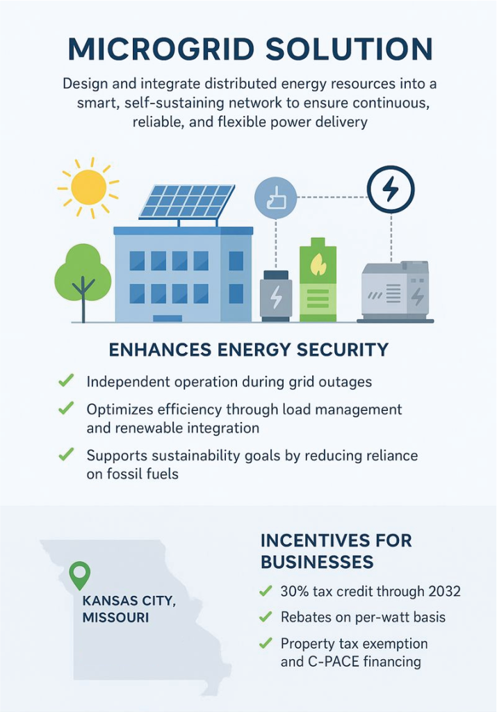
Implementing a microgrid solution to provide holistic resiliency to the building-wide electrical system involves designing and integrating distributed energy resources (such as solar PV, Fuel Cell, battery storage, and backup generation) into a smart, self-sustaining network. This approach enhances energy security by enabling the building to operate independently during grid outages, optimizes efficiency through load management and renewable integration, and supports sustainability goals by reducing reliance on fossil fuels. The microgrid ensures continuous, reliable, and flexible power delivery while creating a future-ready infrastructure that safeguards occupants, operations, and critical systems.
A preliminary solar panel layout was developed to estimate the facility’s potential power generation. The combined system capacity across the north lots and the northeast and southeast estates is approximately 1,780 kW. For comparison, the provided Evergy utility bill from August 2024 indicated a facility demand of 1,570 kW. Based on these values, the proposed solar capacity is projected to adequately meet the facility’s load requirements.
For a campus-wide backup generator power solution, the design would incorporate three 1MW generators. All three would operate in parallel with two sufficient to support the current campus load, while the third unit would serve as a redundant backup, ensuring continued operation in the event of a generator failure.
A potential system interconnection point for either microgrid solution has been identified and shown on the one-line diagram.
Businesses in Kansas City, Missouri can take advantage of a strong mix of federal, state, utility, and local incentives to reduce the cost of commercial solar projects. At the federal level, the Investment Tax Credit (ITC) provides a 30% tax credit on system costs through 2032, while MACRS accelerated depreciation allows businesses to recover much of the investment within the first few years. Missouri further supports solar adoption with a property tax exemption that excludes added system value from assessments and net metering through Evergy, which credits excess electricity generation back to utility bills. Evergy also offers rebates on a per-watt basis, helping reduce upfront installation costs. Kansas City bolsters adoption through the Kansas City Energy Project, which provides technical assistance, and streamlined permitting for solar systems. For financing, commercial property owners can use C-PACE (Commercial Property Assessed Clean Energy) to cover up to 100% of project costs with long-term, property-tax-based repayment, ensuring positive cash flow without upfront capital. Together, these grants, tax credits, rebates, and financing mechanisms create a comprehensive pathway for KCMO businesses to pursue sustainable, cost-effective solar energy.
FIGURE 4 – Microgrid Solution
Submetering
We recommend installing electrical submetering, as indicated on the one-line diagrams, to provide detailed monitoring of major facility loads as well as all loads connected to the generator. Submetering would give the facility the ability to track energy usage by building area or system type, identify high-demand equipment, and better understand how power is distributed throughout the campus. It would also allow staff to monitor generator-connected loads more accurately, helping assess real emergency load demand, verify capacity, and support operational planning. Overall, adding submeters creates a clearer picture of how the electrical system performs, enabling more informed decisions regarding energy management, maintenance, and future infrastructure improvements.
TABLE 2 – Recommended Improvements Summary
This table summarizes the museum’s major building systems. More detailed technical descriptions are available below for readers who want deeper insight.
| System | Recommendation | Primary Benefit |
| Fire Alarm System | Replace Simplex 4100U with Simplex 4100ES or equivalent modern addressable system. | Improves life-safety compliance, expands system capacity, enables modern diagnostics, networking, and long-term support. |
| VESDA System | Upgrade legacy Simplex VESDA to VESDA‑E while reusing existing sampling tubing. | Provides earlier and more reliable smoke detection with fewer false alarms and allows future campus expansion. |
| Electrical Equipment | Replace obsolete and non-compliant panelboards; relocate and centralize electrical distribution where feasible. | Enhances safety, code compliance, and maintainability while simplifying future upgrades. |
| Life Safety Generator | Separate life-safety and non-life-safety loads using two dedicated ATS units. | Achieves code compliance and improves reliability of critical life-safety systems during maintenance or outages. |
| Lighting Systems | Implement campus-wide LED retrofit with modern networked lighting controls. | Reduces energy use and maintenance while improving lighting quality, control flexibility, and occupant comfort. |
| Microgrid / Resiliency | Implement a campus-wide microgrid incorporating solar, storage, and backup generator. | Increases energy resiliency, supports sustainability goals, and enables continued operation during grid outages. |
| Submetering | Install electrical submeters for major loads and generator-connected systems. | Improves energy visibility, validates emergency load capacity, and supports informed operational planning. |
Conclusion
The Nelson-Atkins Museum of Art’s electrical, lighting, and fire alarm systems were comprehensively evaluated as part of the NEH-funded infrastructure improvement effort, revealing a mix of robust but aging equipment across the campus. The facility benefits from dual 15kV utility feeds, large-capacity switchgear, a dedicated generator, and selective LED lighting upgrades, but many panelboards, legacy lighting systems, and fire alarm components — including the Simplex 4100U panel and older VESDA units — are past their service life, difficult to maintain, or no longer code compliant. To address these issues, we developed recommendations that include upgrading to modern systems such as the Simplex 4100ES and VESDA-E detection systems, replacing outdated electrical equipment, separating life-safety and non-life-safety generator loads, implementing a campuswide LED and advanced lighting control modernization, and expanding system resiliency through submetering and an optional microgrid with solar generation and multiple backup generators. Together, these upgrades would significantly enhance reliability, efficiency, safety, and long-term operational flexibility for the museum’s campus infrastructure.
Summary of Mechanical, Plumbing, Fire Protection
Gibbens, Drake, Scott, Inc. (GDS), working with BNIM, reviewed the museum’s major building systems — especially heating and cooling, humidity control, plumbing, and life-safety systems. The goal was to understand how well these systems support the museum’s needs today and identify practical upgrades that can improve reliability, reduce operating costs, and strengthen resilience.
Key Takeaways
Humidity control needs modernization.
The museum currently adds humidity using steam boilers and in-duct steam devices. This approach has been reliable, but much of the equipment and piping is aging. It also uses significant energy and can contribute to maintenance issues as components wear out.
Air-handling equipment is mixed, aging, and inconsistent.
The campus includes air-handling systems from multiple eras — some dating back many decades, others more recent. Some units fall short of today’s expectations for ventilation, filtration, and efficiency. A phased plan is needed to repair, upgrade, and replace equipment over time while maintaining stable temperature and humidity for visitors and collections.
The central utility plant is approaching end of life.
The central plant supplies steam, hot water, and chilled water to campus buildings. Much of the major equipment was refurbished in 2001 and is now near the end of its useful life. Some cooling equipment uses older refrigerants and dated technology. Upgrading the plant is expected to improve efficiency, reliability, and long-term maintainability.
Water fixtures and piping present both efficiency and maintenance opportunities.
Many fixtures reflect older, higher-flow standards and could be replaced with modern water-saving options. Some wastewater and grease-related piping is also prone to backups and leaks. Improvements can reduce potable water use and reduce the risk of disruptions.
Rainwater and other non-potable water sources could reduce irrigation demand.
The campus has significant roof and site area that could collect stormwater for reuse (with appropriate filtration and treatment). Reclaimed water could cover a portion of irrigation demand. Greater reductions would require landscape and irrigation changes toward more drought-tolerant planting.
Better controls can reduce waste and improve resilience.
Modernized controls can help systems “work only as hard as needed,” rather than running at full output all the time. Recommended strategies include temperature resets, smarter ventilation based on indoor air quality, and optimizing fan and pump operation—reducing energy use while protecting indoor conditions.
Key Performance Indicators (KPIs)
These KPIs are categorized based on the primary performance metrics and that influence the building systems efficiency.
TABLE 3 — Comprehensive Building Systems KPI Table
| KPI Category | |
| 1. Energy & Carbon Performance | |
| Specific KPIs | |
| Insulation – Distribution | Improved materials and efficiency metrics |
| Insulation – Equipment | Improved materials and efficiency metrics |
| Failed components | Improved efficiency metrics. |
| Dated / Sunset Technology | Improved efficiency metrics. |
| Dynamic System Response | Added system life and improved efficiency |
| System Distribution Methods | Improved materials and efficiency metrics |
| Shared Energy Systems | Energy recovery and thermal storage metrics |
| 2. Durability & Resilience | |
| Specific KPIs | |
| Moisture Management and Control | Building Perimeter |
| Updated Controls | Dynamic response to improve efficiency and system life |
| Updated Plumbing | Reduce potable water demand |
| 3. Climate Adaptation KPIs | |
| Specific KPIs | |
| Greywater Collection | Drought Severity |
| Extreme condition models | Stress evaluations of HVAC systems for potential future |
| Utility reliance reduction | Energy storage systems with failure redundancies |
| 4. Indoor Environmental Quality (IEQ) | |
| Specific KPIs | |
| Moisture Management and Control | Indoor pollutant control |
| Hard water | |
TABLE 4 — Humanities/Institutional Administrator KPI Framework
(“What We Evaluate”)
| KPI Category | What This KPI Includes (Plain-Language Description) |
| Durability and Climate Resilience | How well would the building system withstand equipment failure until facility personnel could get the systems fully functional. Equipment failure could be due to typical wear and tear, maintenance, or climate related stresses. |
| Moisture Control | How effectively proper humidification control can damage systems and spaces. |
| Climate (Equipment-Related) | How upgrading and remediating units for better performance affects energy use, Includes anticipated kWh savings. |
Current Campus Performance:
The Bloch building was an addition to the west of the Nelson Atkins Museum of art. It opened approximately 18 years ago, but the equipment was purchased prior to opening and is now 20 years or older. With thousands of people visiting each year, the building systems will require technological improvements and repair or replacement of existing aged equipment. The existing systems operate inefficiently intended to target continuous condition control. The existing utilities are billed at preferred rates making efficiency comparison cost justification longer to return on investment.
Current Utility Expense:
| 2023-2024 | Jan | Feb | Mar | Apr | May | Jun | Jul | Aug | Sep | Oct | Nov | Dec | Sum |
| Historical Utility Data | |||||||||||||
| kwh | 678,658 | 706,402 | 712,114 | 712,934 | 795,924 | 859,847 | 844,569 | 859,179 | 896,023 | 712,400 | 712,748 | 773,609 | 9,264,406 |
| $ | $55,356.21 | $55,823.93 | $56,115.00 | $56,009.86 | $68,190.19 | $85,928.94 | $79,128.06 | $81,925.00 | $79,855.52 | $64,599.53 | $55,051.66 | $57,459.12 | $795,443.02 |
| $/kwh | 0.082 | 0.079 | 0.079 | 0.079 | 0.086 | 0.100 | 0.094 | 0.095 | 0.089 | 0.091 | 0.077 | 0.074 | $0.09 |
| gas (MCF) | 6,993 | 6,184 | 6,372 | 6,014 | 5,666 | 4,895 | 4,904 | 5,255 | 5,292 | 5,838 | 6,213 | 6,625 | 70,251 |
| $/MCF | $5.00 | $5.00 | $5.00 | $5.00 | $5.00 | $5.00 | $5.00 | $5.00 | $5.00 | $5.00 | $5.00 | $5.00 | $5.00 |
| gas (therms) | 72587.34 | 64189.92 | 66141.36 | 62425.32 | 58813.08 | 50810.10 | 50903.52 | 54546.90 | 54930.96 | 60598.44 | 64490.94 | 68767.50 | 729205.38 |
| $ | $36,293.67 | $32,094.96 | $33,070.68 | $31,212.66 | $29,406.54 | $25,405.05 | $25,451.76 | $27,273.45 | $27,465.48 | $30,299.22 | $32,245.47 | $34,383.75 | $364,602.69 |
| $/therm | $0.50 | $0.50 | $0.50 | $0.50 | $0.50 | $0.50 | $0.50 | $0.50 | $0.50 | $0.50 | $0.50 | $0.50 | $0.50 |
Central Utility Plant Improvements:
- Packaged DX air cooled or condenser cooled equipment is unable to meet the energy efficiency requirements of the Museum. These systems are considered less efficient.
- Heat Recovery Chiller delivers the largest energy reduction, reducing both electricity and natural gas. Modifications to the existing plant and system are required to achieve. Temporary conditions and equipment will be needed during the transition.
- Direct Chiller replacement straight forward reliable savings with the least complexity and cost. Minimal modification is necessary, but temporary cooling equipment will be needed during the transition.
- Economizer HX improves cooling efficiency incrementally but offers less heating reduction. Modifications to the existing plant and system are required to achieve. Temporary conditions and equipment will be needed during the transition.
- Storage Source Heat Pump solution eliminates natural gas, increases complexity, adds thermal storage, and aids utility resilience. Electrical needs can be offset by grid and generation strategies. A new plant constructed adjacent to the existing is necessary.
- Geothermal + Chiller provides the same as the Storage Source Heat Pump Solution, however increased efficiency and system resilience is obtained at the cost of distributed infrastructure.
- New Chiller Baseline was considered as the code minimum modification.
Please refer to Central Utility Plant Options for Deeper context, comparisons, and conclusion.
Existing System Observations
Insulation:
Piping:
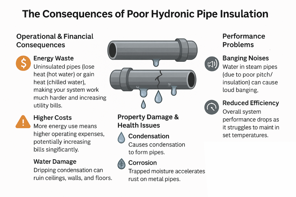
Multiple locations lack proper piping insulation on mechanical system piping and valving, as well as domestic water systems are subject to condensation, resulting in moisture control damage, corrosion damage, energy loss and system strain.
- Several access panels beneath HVAC valving are shown with moisture damage. Valving and piping are not insulated resulting in condensation forming and creating damage.
- System experiences leaking through multiple steam grid humidifiers. These leaks are damaging system insulation and have resulting in water leaking from ductwork. Ductwork, piping, insulation, valving, etc. all require repair or replacement with system improvements to mitigate future water damage. New system technology to remove steam humidification system and replace with an alternate steam delivery method (adiabatic humidification, etc) should be considered which pose less wear on system components while being more efficient.
FIGURE 5 – Consequences of Poor Pipe Insulation
Equipment:
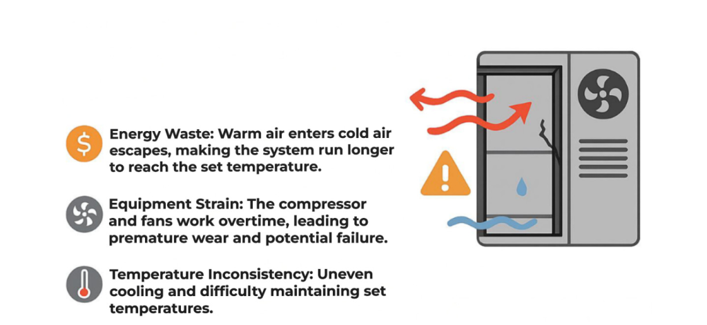
Existing equipment shows wear and tear resulting in unit working harder and decreases the efficiency of the unit.
FIGURE 6 – Consequences of Poor Equipment Insulation
Condensation & Moisture Control:
The Museum is humidified and requires moisture control. Additionally, the museum has several locations that require improvements and repair due to condensation moisture damage.
- Lens cavities channel glass locations exposed to interior location found with condensation formation.Indoor perimeters for Lens 1 have caulking that is becoming undone or deteriorating.
- Condensation accumulates in vestibules.
- Building perimeter along all lenses shows leak damage due to moisture formation.
- Vapor barrier in different locations of the building has been compromised due to water leaking in from the outside.
- Envelope deficiencies in building due to leaks from lack of thermal breaks, ineffective insulation, and limited air circulation. Consider acquiring indoor air quality controls.
FIGURE 7 – Building with No Vapor Barrier and Building with Vapor Barrier
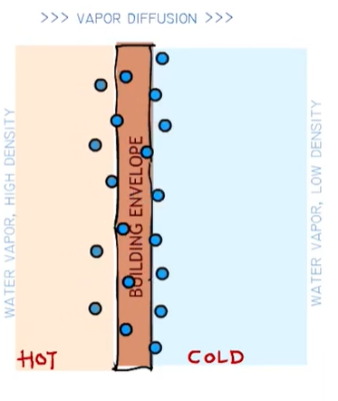
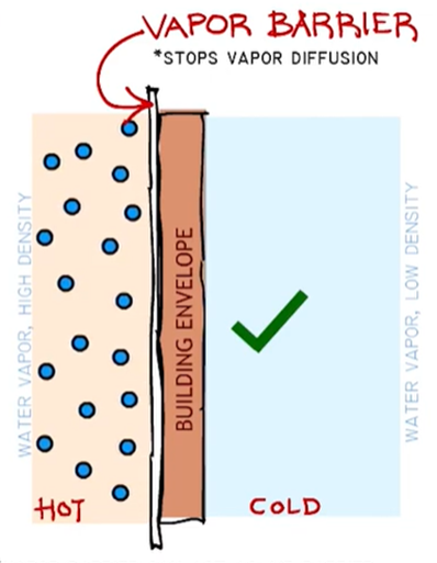
Weather Barrier Vs Air Barrier Vs Vapor Barrier – What’s the difference?
Component Failure and Upgrades
The Bloch building opened in 2007. Most HVAC equipment has a lifetime of 15-30 years depending on factors such as, where the unit is located (outdoor or indoor), climate type, usage patterns, maintenance frequency, etc. Many of the systems mentioned below are reaching their end of life or will need major part replacement and upgrades to ensure the overall integrity and effectiveness of the building systems.
- Steam room has multiple components and piping that has failed due to corrosive nature of fluids.
- Flow from chilled water or steam is causing corrosion throughout the building in the pipes and at the drains. Both sources of water are higher purity and have a greater potential to rust ferrous components.
- Existing exhaust and return air systems Existing assemblies are large motor equipment resulting in challenging repair when failed.
- Louver intakes are large debris and bug screens that serve to protect the Museum as outside air is brought in. Louvers were found to be damaged, broken, and dirty.
- Multiple bucket traps throughout the building are non-operable. Bucket trap proper operation required for utility of steam system.
- Diffusers throughout Lens 1 are missing hardware and are blocked with debris which could decrease effectiveness or air distribution.
Outdated Controls:
- Lighting wall switches and HVAC thermostat control offers minimal control and no response display. Calibration may be required.
- Existing building management system is at end of life. Replace control hardware that is at end of life or not working, and upgrade building management system. Existing system is pneumatic with air compressors supporting operating valving found to be worn and rusted.
Water Use – Indoor and Outdoor
- Several domestic water piping assemblies lack insulation. The Museum is humidified and the water temperature is likely to condense moisture from the air without insulation.
- Drainage piping, plumbing fixtures, drains, and system components found rusted and worn.
- Piping calcification: Existing plumbing fixtures show visible calcium at outlet. Several aerators no longer present. Water piping may be beginning to collect interior piping calcification.
- Multiple bathroom locations lack clean outs for fixtures. Piping for these fixtures are subject to build up. No water softener, passive or active, is present at the Museum. The calcium formation is likely present within the piping system resulting in reduced flow and other system issues.
- Several sink locations without backflow prevention. Potable water supply may be subject to cross contamination. Annual testing and should be tested for compliance.
- Verify operation of water heaters, and pumps. Repair insulation and upgrade water heaters at end of life with new heat pump water heater technology, along with filters, and valves where appropriate
- Verify operation of pumps. Replace pumps, filters, valves and piping where appropriate.
- Lens 1 Café:
- Requires bottle chain assembly for industry recommended control of bottled gasses. include gas sensors for nitrogen and CO2 for local alarming.
- Multiple roof drain locations have notable corrosion within the drain bodies as well as the clamping rings supporting the drains.
- Replace existing fixtures with fixtures that have some type of water efficiency capability.
FIGURE 8 – Benefits of Low Flow Faucets
The Benefits Of Low-Flow Faucets: Saving Water And Money » Faucet Wizard

Pictures of Existing System’s Major Issues
Energy Savings
Insulation:
From site observations, we believe that 20% of each institutions’ hydronic piping insulation is damaged. Damaged or missing piping leads to energy losses, reduced efficiency, and higher energy costs due to the system overcompensating to maintain the set temperature. Below is a summary table of operational costs due to insufficient insulation.
| BLOCH | |
| Estimated Pipe Length (ft.) | 16,000.00 |
| Estimated Damaged Pipe (%) | 20 |
| Annual Energy Loss (BTU/hr) | 35,821.07 |
| Annual kWh Lost | 1,070,032.65 |
| Annual $ lost | 128,403.92 |
| Nelson Atkins | |
| Estimated Pipe Length (ft.) | 26,000.00 |
| Estimated Damaged Pipe (%) | 20% |
| Annual Energy Loss (BTU/hr) | 37,530.24948 |
| Annual kWh Lost | 1,121,088.60 |
| Annual $ lost | 134,530.63 |
Equivalent trees that would need to be planted to offset kWh loss: 514,701.4
Kwh To Co2 Calculator – Glow Calculator
Humidification and Moisture Control
Nelson Atkins and Bloch buildings currently use steam humidifiers for the humidification and moisture control of their buildings. From site observations, there are elements of the steam humidification system that are no longer operable in the Bloch and Nelson Atkins buildings that decreases the efficiency of the system. Although a higher upfront cost, adiabatic humidification would be recommended. Not only would this save carbon emissions and operating costs due to the decrease in steam generation, over the system’s life energy costs and water costs would also decrease due to most of the energy generation in adiabatic humidification coming from pump energy. Additionally, water could be re-used either in an RO reclaim system, or can be another source of grey water.
| Humidification – | ||||
| TOTAL (LBS/HR) | TOTAL (BTUs/HR) | YEARLY (GALLONS) | YEARLY ($) | |
| BLOCH | 950.70 | 1,093,305.00 | 470,073.43 | 7,051.10 |
| NAMA | 1,453.13 | 1,671,099.50 | 718,499.84 | 10,777.50 |
| TOTAL | 2,403.83 | 2,764,404.50 | 1,188,573.27 | 17,828.60 |
| HOURLY (KWH) | HOURLY ($) | YEARLY (KWH) | YEARLY ($) | |
| BLOCH | 323.57 | 25.89 | 970,722.32 | 77,657.79 |
| NAMA | 494.58 | 39.57 | 1,483,733.80 | 118,698.70 |
| TOTAL | 818.15 | 65.45 | 2,454,456.12 | 196,356.49 |
| HOURLY (MCF) | HOURLY ($) | YEARLY (MCF) | YEARLY ($) | |
| BLOCH | 1.61 | 8.05 | 6,440.68 | 31,237.29 |
| NAMA | 2.46 | 12.31 | 9,844.47 | 47,745.70 |
| TOTAL | 4.07 | 20.36 | 16,285.15 | 78,982.99 |
| Total $ Spent on Steam Humidification | 293,168.07 |
Fan Array Retrofits
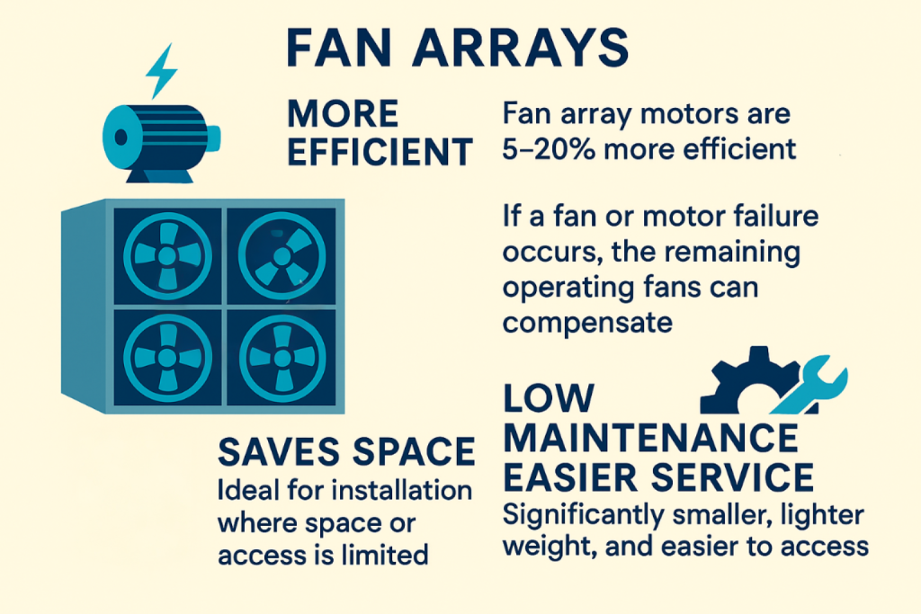
The energy required for distributing heating and cooling, heat rejection, and ventilation inside a commercial building accounts for roughly 25% of the energy consumed in the United States. [1] Out of that load, 50% of the energy consumed by supply fans. [2] Multiple smaller fan array systems will also provide redundancy and resilience, for if one fan’s motor fails; the rest of the fans will increase motor power until failed fan motor is fixed. This ensures the comfortability of occupants and decreasing degradation of equipment and objects stored within the institutions. When all fans are working, they operate part load, leading to higher energy savings due to HP reduction, via fan law. Updating or retrofitting units with will accumulate to energy savings. Additionally, the local utility company has a rebate program for retrofits and upgrades that each institution can take advantage of and have even higher savings.
Energy Savings from Fan Arrays – Full Load
| Nelson-Atkins & Bloch | Full Load | KWH/YR |
| Fan Array HP Total | 896 | 10,525,628.74 |
| Existing HP Total | 960 | 11,277,459.37 |
| Savings Full Load | $ 90,219.67 |
FIGURE 9 – Fan Arrays Efficiency
Other System Improvements – Greywater Capture
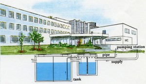
In the Kansas City area, the maximum number of consecutive dry days is set to increase from 30.9 days to 39.5 days per year. To increase the resiliency of campus and prepare for these dry events, we initially recommended rainwater capture and HVAC equipment condensation capture, specifically for non-potable applications such as irrigation and flushable water fixtures. The rainwater would be collected from the NAMA and Bloch roofs, and potentially other non-pervious surfaces where appropriate. The captured water would be stored throughout the campus in storage tanks, closest to the irrigation systems water lines. This water would be filtered and treated in the storage tanks before being re-used.
FIGURE 10 – Example of rainwater capture in commercial building. Tanks can be stored underground or in mechanical equipment rooms as necessary. [3]
For an accurate design it is important to understand how the weather data is estimated. For this calculation, we used historical NOAA data for the last two decades which utilizes gamma statistical distribution. All rainwater rates will subtract 0.08 in/month from the monthly rainwater rate due to imperviousness factors of roofs.
Using existing utility data over the last 3 years, we evaluated that rainwater capture would be able to offset 15-20% of the Nelson Atkins and Bloch’s average annual irrigation water usage. 50 gallons/hr of additional greywater capture from condensation can be achieved from the units at both Nelson Atkins and Bloch.
| Nelson Atkins & Bloch Buildings | In/Month | Precipitation Days | Volume (gal)/Precipitation Month |
| Jan | 0.66 | 1.70 | 48,124.90 |
| Feb | 0.83 | 2.70 | 62,023.00 |
| March | 1.16 | 6.50 | 89,354.43 |
| April | 1.93 | 9.40 | 152,119.42 |
| May | 2.99 | 12.60 | 239,320.14 |
| June | 2.26 | 12.50 | 179,579.42 |
| July | 2.49 | 10.30 | 198,353.86 |
| Aug | 3.04 | 9.70 | 243,807.10 |
| Sept | 2.06 | 8.90 | 163,405.58 |
| Oct | 2.78 | 6.80 | 222,721.45 |
| Nov | 1.50 | 4.60 | 116,867.45 |
| Dec | 1.10 | 2.70 | 83,698.54 |
| Annual | 22.81 | 88.40 | 1,871,856.30 |
To further aide the Nelson Atkins and Bloch facility teams in reducing their outdoor water use and conservation practices , they may also consider:
- Water Efficiency: systems that adjust watering schedules based on local weather conditions reduce water waste. Drip irrigation also helps with deep watering, reducing the amount of times plants need to be watered.
- Plant Selection: choosing native and drought-resistant plants reduces the need for irrigation as they have adapted to locate climate conditions and may require less water.
Although rainwater capture cannot offset all the irrigation water usage, conservation of water plays a crucial role in climate adaption. Other environmental benefits to collecting rainwater include: [4]
- Preventing flooding and erosion: rainwater collection reduces the volume of runoff water that can lead to flooding and erosion during heavy rainfall events.
- Conserving Energy: Water that is delivered from a water treatment plant has more carbon emissions associated with water treatment and transportation.
- Reducing Water Demand: Harvesting rainwater onsite reduces demand from municipal water supplies and helps conserve water resources.
Using utility information over the past eight years, we evaluated that rainwater capture would be able to offset 100% of the Linda Hall Library’s average annual irrigation water usage. At this point in time, condensate capture from equipment would be a secondary as it is not needed for system justification.
Recommendations
| Issues: | Solution: |
| Insulation leak and damages | Insulation repairs are recommended. |
| Equipment shows wear and tear, and insulation is degrading. | Repair unit to decrease energy waste and equipment strain. Reseal and refurbish all AHUs. Provide new door gaskets. Provide condensate pan repair. Provide plenum rated internal sealing of exposed metal. Repair all corrosion on supporting accessories. Provide new sensors with calibration. |
| Condensation accumulates in vestibules | It is recommended to update the HVAC in the vestibules to an isolated system to avoid condensation. |
| Caulking undone around perimeter of multiple Lenses | It is recommended that the perimeter is resealed with caulking to avoid more condensation formation. |
| Leaking from compromised vapor barrier | Patch the outdoor penetrations and re-insulate piping. |
| Failed piping due to corrosive nature of steam and chilled water fluids | Replace and upgrade with stainless steel and non-corrosive materials where appropriate. Sanitary piping system needs to be investigated, identified, and replaced / repaired where necessary. |
| Louvers were found to be damaged, broken, and dirty. | Clean, repair, and replace where necessary. |
| Existing exhaust, return, and supply air systems are large motor assemblies | Replace multiple exhaust and return air fan systems with direct drive fan wall assemblies. |
| Diffusers in Lens 1 are missing hardware or unclean. | Clean, repair, and replace where necessary. |
| Multiple bucket traps throughout the building are non-operable | Investigate all bucket traps and replace where necessary. |
| Existing building management system is at end of life. | The system lacks current cyber security protections that are strongly recommended to be included in the new building management system. |
| Several domestic water piping assemblies lack insulation. | Insulate to preserve energy. |
| Piping, fixtures and piping rusted and worn. | System repair where pipes are leaking, rusted and worn. |
| Piping calcification | Consider expanding water softener system |
| Several sink locations without backflow prevention. | Provide backflow preventers and Annual testing for compliance |
References:
[1] Energy Consumption Characteristics of Commercial Building HVAC Systems
[2] Air Handling Units: Energy Efficiency Measures | HVAC Resource Map
[3] Benefits of Rainwater Harvesting for Commercial Buildings | E-Landscape Specialty Solutions, LLC
[4] Environmental Benefits of Rainwater Harvesting & Rain Barrels